Moderating the impact of integrating water-cooled servers into data centres
The primary cooling method for IT equipment housed inside the world’s data centres involves use of air cooling. This trend may be shifting to liquid cooling as customers of IT equipment are increasingly being driven by scientific computing to support artificial intelligence (AI) and high performance computing (HPC). With each new generation of IT equipment, manufacturers are being pushed to increase their processing capability (resulting in more heat being generated) and explore more effective means of cooling. The heat generated is starting to bump up against the limits of conventional air-cooling approaches.
Carbon call-out
Air cooling has worked well for systems that deploy processors up to 150W, but IT equipment is now being manufactured with processors well above 150W where air cooling is no longer practical. The power for one company’s graphics processor unit (GPU) is currently at 300W. Another company produces a CPU announced at 205W and a many integrated cores (MIC) GPU announced at 320W.
Not only are processors pushing designs to use water cooling, other components, such as memory and voltage regulators, supporting these processors are also pushing into the realm of liquid cooling. The 2018 Supercomputing (SC18) show in Dallas clearly showed the adoption of liquid cooling is on the upswing, with displays from most of the major IT manufacturers displaying their liquid-cooling products, but also a number of vendors showing server-oriented liquid‑cooling technologies.
Liquid cooling is far more efficient than air cooling in terms of heat transfer. It is also more energy efficient, reducing electrical energy costs significantly. Being more energy efficient reduces the carbon footprint and contributes to the goals of being “green” in the operation of the data centre. Liquid cooling can eliminate the need for additional racks, creating higher data centre server densities using less space. Also, liquid cooling can allow higher processing speeds – CPUs and other components can run cooler using liquid cooling. Designing with liquid cooling can reduce or eliminate the need for air-moving devices, thereby decreasing the noise levels in the data centre (which in many cases are approaching OSHA limits). And finally, liquid cooling can provide a more uniform cooling of the components compared to air cooling, improving the reliability of the system.
With these factors in mind, ASHRAE TC 9.9, Mission Critical Facilities, Data Centres, Technology Spaces and Electronic Equipment, has recently published a 45-page white paper Water‑Cooled Servers – Common Designs, Components, and Processes (available for free at https://tinyurl.com/y239t4rv). With the advent of more water-cooled IT products arriving in the marketplace, TC 9.9 felt the need to outline some of the common processes, parts and materials that could provide focus for use in future water-cooled designs and help accelerate the trend toward increased use of water-cooled servers deployed in data centres.
Obviously, some parts in a water-cooled IT system will be specific to the product design, such as cold plates, manifolds, arrangement of piping, pumps, valves, etc., but some things like quick connects, hoses, hose connections, wetted materials, filtration, pressure testing of final water-cooling assemblies, water chemistry and design options to integrate water-cooled IT equipment into the data centre cooling infrastructure fall more into the category of common parts/ processes that could be used by all current and potential manufacturers of water-cooled IT equipment.
The TC 9.9 white paper effort is an attempt to provide and make available those items that could be classified as common. Several of these will be discussed in this article. The remainder of this article, as well as the white paper, are focused on the implementation of water-cooled IT equipment. Other liquid‑cooling technologies for IT equipment are available, and in general these liquids will be associated with the technology cooling system loop (TCS) for the IT equipment, while the water‑cooled facilities loop (facility water system [FWS]) will still be required to remove the heat from the liquid-cooled TCS loop.
The data in the white paper displays some trends, including that of 28 water-cooled products announced by IT OEMs from 2010 to 2017 (Figure 1). The vertical axis is the server power divided by the rack footprint. Variations in rack height are not accommodated in this figure, but it is noted that there was not a large variation of rack heights. One other caveat in the denominator for the area is that if the water-cooled server rack required a coolant distribution unit (CDU) (see the section below for a description of the CDU implementation into a data centre) then this area was apportioned to the rack area. For example, if a CDU supported four server racks then 25% of the area of the CDU was added to the rack area to make up the denominator for power/rack footprint.
Each bar in Figure 1 displays the total maximum heat load dissipated by the water-cooled server rack. (For comparison, the trend of the maximum air-cooled servers [scientific servers] as displayed in the latest ASHRAE Datacom Series book IT Equipment Power Trends, 3rd Edition is also shown in Figure 1.) The amount of power dissipated is categorized into three areas: air cooled, indirect water-cooled and direct water‑cooled. These are defined as follows:
- Air Cooled: power that is transferred directly to the room air and cooled via traditional data centre cooling.
- Indirect Water-Cooled: power that is transferred indirectly to water through an air-to-water heat exchanger located within or on the rack (for example, a rear door heat exchanger).
- Direct Water-Cooled: power that is transferred directly to an attached heat transfer component like a cold plate.
Water cooling with and without a CDU
For those unfamiliar with water-cooled IT equipment, the first question will be: How does one transfer the heat from the water-cooled IT equipment to the facilities water system (FWS)? The most common form of water-cooling implementation within the data centre today uses a coolant distribution unit (CDU) to separate the facility water system (FWS) from the technology cooling system (TCS) by using a water-to-water heat exchanger. By using a water-to-water heat exchanger, the CDU can reject heat from IT equipment (ITE) without exposing the sensitive IT cooling components to the typically less regulated FWS water.
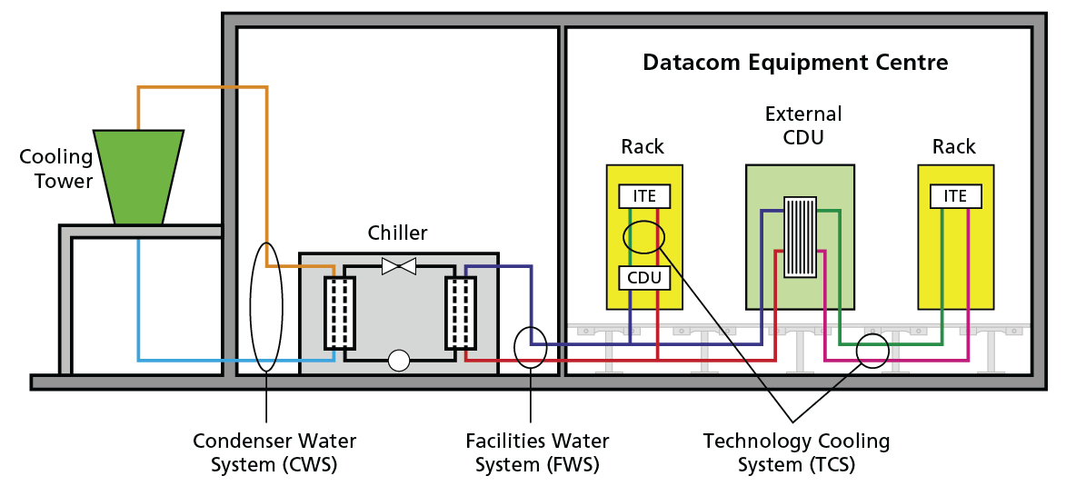
Figure 2 – CDU Liquid cooling system within a data centre.
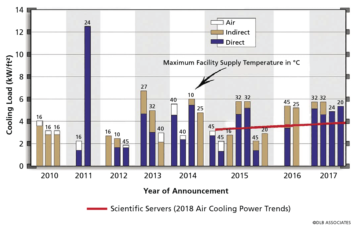
Figure 1 – Water Cooling Load Trends from 2010 to 2017. Footprint includes apportioned CDU area. Data shown with permissions from HPE, SGI, Fujitsu, IBM, Dell, Huawei and Cray.
Water cooling with and without a CDU
CDUs may be located within an IT rack, providing TCS water distribution to equipment within a single rack, or installed as a floor-standing external unit that distributes TCS water to a plurality of racks. Figure 2 displays both examples showing the heat transfer from the water‑cooled server rack through the water-to-water heat exchanger in the CDU. The basic flow and heat exchange components within a CDU consist of a heat exchanger, flow-mixing valve, pumps, expansion tank and water supply/return manifolds. The temperature of the water in the TCS loop is controlled by using a mixing valve to regulate the fraction of water from the FWS loop to pass through the water‑to‑water heat exchanger and forcing the remainder to bypass the heat exchanger.
The CDU plays an important role in data centre liquid cooling by often providing the following functions:
- Transfer heat from the TCS to the FWS;
- Circulation of TCS coolant;
- Allows for a TCS coolant other than water (e.g., refrigerant or engineered fluid);
- Prevents condensation within the IT equipment by regulating TCS water above room dew point;
- Establish and maintain a coolant quality and chemistry different from that associated with the FWS and more suitable to the TCS; and
- Flexible coolant temperature supplied to ITE.
There are some scenarios, however, where coupling ITE directly to FWS can be advantageous. This is referred to as a “Non-CDU” water-cooling implementation. Figure 3 shows an example of a data centre liquid-cooling system that couples the facility water supply (FWS) directly to the ITE. In this figure “FFU” references a facility filtration unit, and “RFU” references rack filtration unit.
Some of the key advantages of a non-CDU implementation include:
- Increased data centre floor space or IT rack space;
- Closer coupling of ITE heat sources with final heat dissipation medium (reduced thermal resistance);
- Shared pumping redundancy; and Improved liquid-cooling efficiency
- Reduced number of fluid movers;
- Typically, higher facility-side ΔT (lower flow rate)
- by removal of CDU approach temperature.
While the benefits of a non-CDU implementation are attractive, they do require increased up-front design consideration, specifically in the realm of water quality, material selection and filtration.
In both cases described above the water that is supplied to the rack or cabinet needs to be above the room dew point. ASHRAE Datacom Series book Thermal Guidelines for Data Processing Environments, Fourth Edition (ASHRAE 2015) specifies a maximum dew point of the room for a Class A1 environment of 17 C. Two techniques can be used to maintain TCS supply temperatures above the dew point:
- set the control point of the TCS cooling loop above the Class A1 environmental specification of 17 C, or
- have a supply temperature controlled such that it is adjusted a set amount above the measured room dew point.
Because of the increased focus on energy savings, consideration must be given to those extremes in ambient temperature and whether the water-cooled IT equipment can be adequately cooled with the water temperature supplied by an economizer type FWS.
Water Quality
For a non-CDU water-cooling solution, ITE must be designed with liquid handling components that are compatible with the water quality of a facility water supply (FWS). Due to the potential presence of harsher chemical constituents, the materials will often need to be of a higher quality than their TCS‑wetted, CDU counterparts.
A good reference for water quality and wetted material recommendations can be found in Chapter 5 of the ASHRAE Datacom Series book Liquid Cooling Guidelines for Datacom Equipment Centers, Second Edition.
For CDU implementations, only the primary-side of the CDU heat exchanger needs to be compatible with water quality of the FWS. The secondary side as well as the ITE itself can be designed to the much more tightly controlled water quality definitions of the TCS loop (see Chapter 6 of Liquid Cooling Guidelines for Datacom Equipment Centers, Second Edition).
Filtration
In addition to water quality and wetted material compatibility considerations, another key design tenant for the facility planning either a CDU or non‑CDU water-cooling implementation is filtration. In both cases, the facility water supply should be filtered at the supply side of each device interface in accordance with the needs of the implemented devices.
CDU-based implementations utilising a liquid-to-liquid heat exchanger between the FWS and TCS loops require filtration on the supply side of the FWS loop that provides sufficient particulate removal to prevent buildup of solid matter between its internal heat transfer surfaces (typically stacked flat plates). This spacing is typically between 2mm and 8mm.
Non-CDU implementations bring facility water directly into the ITE for heat exchange that typically takes place using a cold plate. While cold plates utilised within a TCS loop will often have fin spacing that is only a few tenths of a millimeter to maximize heat transfer surface area, cold plates designed for non-CDU use will necessarily require larger fin spacings to prevent solid particulate buildup or over filtration of the FWS. Fin spacing for non-CDU cold plates is recommended to be between 0.7 and 1.0mm.
Wetted materials
Proper wetted material selection is just as important as proper water chemistry to ensure the health of the watercooled server. In this context, the term “wetted material” shall reference any material that comes in direct contact with the water-based cooling fluid. Liquid Cooling Guidelines for Datacom Equipment Centers does offer some limited recommendations on wetted materials to avoid and ones to utilize.
It is important to understand these wetted material requirements in context of the two primary designs for deploying water‑cooling servers in a data centre. The two basic water‑cooling systems are described earlier in Water Cooling With and Without a CDU. Maintaining the proper water chemistry, wetted material set, and proper filtration are important for both designs, especially for any water that is in contact with the cooling components. The brief description of these two systems above was important as there are two levels of care that must be taken in integrating these designs within the data centre. For the system that deploys a CDU, the water cooling for the electronics (TCS) is in a separate loop from the facilities (FWS) with the CDU acting as the buffer between the facilities and electronics. In maintaining the server water loop it is somewhat easier in that the IT manufacturer of the system provides the requirements for the water used in the TCS loop, water chemistry and filtration. Additionally, the wetted material set for the TCS loop was chosen by the IT manufacturer for its compatibility to maintain high system reliability.
For systems without a CDU where the data centre facility provides the water directly to the electronics, the wetted materials, water chemistry and filtration are crucial. The client, including their facilities team, the system designer, and the IT equipment manufacturer must all participate in a well-coordinated effort to ensure the long-term reliability of the IT water‑cooling system.
Just to highlight this interaction, the wetted materials for the FWS only allows certain brass alloys and only specific versions of copper alloys when deploying a water-cooled server system. These requirements stem from years of use and would probably not be known without close contact with the IT manufacturer of such equipment.
As new water‑cooling IT equipment is introduced into the data centre environment, it is critical that the exact wetted materials for the entire system is well understood. There are several examples in other industries where a mismatch in materials used led to issues. The emergence of water cooled ITE is no different in that respect. The ITE manufacturers as well as the data centre facilitators must be aligned on the working fluid being used, the material set and the water chemistry plan.
Summary
Water-cooled IT equipment represents a new paradigm for datacom centre operators. As with any new approach to doing things, education will play a large role in the successful implementation of water cooling. Although most of the general rules for current air-cooled implementations apply, datacom centre operators should have cooling contingency plans; implement cooling system redundancy; deploy critical subsystems, such as pumps that have high reliability and availability; and one should place subsystems such as pumps (water, refrigerant, dielectric) and rack-based cooling systems on uninterruptible power supply (UPS). There are, however, some areas of water cooling that require special attention: temperature control, prevention of condensation, TCS water cleanliness, wetted material requirements and water chemistry.
This article was originally printed in the July 2019 edition of the ASHRAE Journal, and is reprinted with permission from ASHRAE.
Go to www.ashrae.org