The importance of external CFD for data centres


This paper discusses the growing importance of external CFD in evaluating and optimising rooftop mechanical layouts for high-density data centres.
Abstract
The rapid adoption of artificial intelligence (AI) workloads is transforming data centre design, driving significantly higher rack power densities and an increase in overall power consumption. This evolution demands a greater number of air-cooled chillers, often installed on constrained rooftop spaces. As a result, chillers are now being arranged in denser configurations with reduced spacing, leading to challenges such as hot air recirculation and wind uplift, both of which can adversely affect chiller intake conditions and overall system performance. In this context, external computational fluid dynamics (CFD) analysis has become an essential design tool. This paper discusses the growing importance of external CFD in evaluating and optimising rooftop mechanical layouts for high-density data centres. It explores how CFD can identify problematic airflow patterns, quantify the risk of performance degradation, and guide informed design decisions. Furthermore, the paper presents a range of effective mitigation measures – such as optimised chiller placement, wind barriers, and elevation strategies – to address airflow issues and enhance cooling reliability. Case studies and simulation results are used to demonstrate how these strategies, when guided by CFD, contribute to resilient and energy-efficient data centre cooling infrastructure.
Introduction
The rise of AI has introduced a fundamental shift in the design and operation of data centres. Unlike traditional applications, AI workloads often demand significantly higher power and cooling densities, resulting in increased heat loads per rack and the need for more expansive data hall deployments. As a consequence, cooling infrastructure must also scale up – both in capacity and in physical footprint. Among the various cooling strategies, air-cooled chillers are a commonly favoured solution due to their ease of deployment, modularity, and reduced reliance on water resources.
However, placing an increasing number of chillers on rooftop spaces – especially in dense configurations – poses a unique challenge. These chillers often operate in tightly packed layouts, constrained by site limitations and architectural considerations. In such scenarios, the interaction between multiple chillers and the external environment becomes critical. Poor airflow, hot air recirculation, and wind effects can significantly compromise the performance of the cooling system. These issues are often invisible during conventional design stages and require advanced simulation techniques for early detection.3,4,5,6
In addition to the chiller layout and prevailing wind conditions, other sources of heat and airflow must be carefully considered to ensure realistic modelling outcomes. Equipment such as generator flues, warm-air plumes from generator radiators, rooftop air handling units (AHUs), and ventilation intake and discharge louvres can all influence local airflow patterns and temperature distributions. The presence of adjacent buildings – particularly if they house their own rooftop heat-releasing equipment – can further complicate the airflow dynamics. If the subject building is positioned immediately downwind of another structure, it may be exposed to elevated temperatures carried by prevailing winds. These factors should be incorporated into the CFD model and weather data inputs, with offsets applied where necessary to represent their impact on the cooling infrastructure accurately.3,4,5,6
This paper explores the application of external computational fluid dynamics (CFD) analysis as a diagnostic and design optimisation tool in these high-density rooftop environments. While CFD is often used internally to analyse airflow within data halls, its external application is becoming increasingly valuable for assessing the performance of air-cooled chillers subject to complex outdoor conditions.
Note: Due to the classified nature of most project work undertaken, this paper does not present data from any specific facility. Instead, it draws upon generalised findings and recurring patterns observed across multiple data centre projects to provide practical design insights.
Purpose of this paper
The aim of this paper is to highlight the critical role of external CFD analysis in the design of rooftop mechanical layouts for data centres utilising air-cooled chillers, especially in the context of high-density AI deployments. The paper is structured to provide:
- A brief introduction to CFD software
- An overview of the external CFD analysis methodology, including tools, modelling approach, and general assumptions
- Findings and results from representative CFD scenarios, focusing on airflow interactions, recirculation effects, and thermal stratification
- Assessment of chiller performance impacts, linking airflow behaviour to temperature rise and efficiency losses.
- Mitigation strategies informed by CFD analysis, such as layout optimisation, wind management features, and spatial planning techniques.
Through these topics, the paper aims to provide a practical reference for building services engineers and data centre designers, advocating for the early integration of CFD in the design process to ensure performance, resilience, and energy efficiency.
Brief introduction to CFD software
Computational fluid dynamics:
- Provides a numerical/computational solution of fluid flow field (usually turbulent) achieved iteratively
- Is two- or three-dimensional
- Is solved in the computational domain, divided into small mesh elements (discretisation)
- Sets boundary conditions – assumed conditions at the boundaries of the domain
- Provides simplified solutions to the conservation equations of mass, momentum, and energy.
The CFD software used for the examples presented in this paper uses the Navier-Stokes equations to solve complex fluid flow and heat transfer problems, based upon the conservation of mass, momentum, and energy.
The Navier-Stokes equations are used to simulate the motion of fluids, such as air or water, in a given physical domain. The equations are solved numerically using a finite volume method, which discretises the physical domain into a large number of small control volumes (mesh). The governing equations are then solved for each control volume, taking account of the fluid properties, boundary conditions, and any other relevant information.
The software offers a wide range of solver options to choose from, including steady-state, transient, and multi-phase simulations. Additionally, it supports a variety of turbulence models, such as the Reynolds-averaged Navier-Stokes (RANS) equations and large eddy simulation (LES), to account for the effects of turbulence in the fluid flow.
Overview of the external CFD analysis methodology
The general design criteria for external CFD simulations are established based on climatic data obtained from the ASHRAE Handbook – Fundamentals. Site-specific weather parameters are sourced through the ASHRAE Weather Data Viewer, which provides comprehensive data including dry bulb temperatures, wind speeds, and directions for global locations.
For hyperscale data centre projects, the dry bulb temperature conditions used in the analysis typically align with ASHRAE’s defined n=20 or n=50 design values. These values represent extreme temperature conditions occurring once in 20 or 50 years, respectively, and are selected to reflect the criticality and resilience requirements of mission-critical infrastructure.
Mean coincident wind speed values are extracted from the same ASHRAE database and used as the input for wind boundary conditions. In terms of wind direction, the predominant direction observed at the site is generally adopted as the primary case for initial modelling. However, to ensure robustness of the design against varied climatic influences, hyperscale data centre clients often require analysis under multiple wind directions. The standard practice includes simulations with:
- Predominant wind direction
- Wind direction parallel to the building façade, and
- Wind direction perpendicular to the building façade.
Note: Some clients may request analysis for more than three wind directions.
The CFD model domain incorporates not only the proposed building and rooftop chiller layout, but also all nearby structures and external equipment that may influence airflow and thermal conditions. This includes a detailed representation of significant heat sources such as generator flues, warm-air plumes from generator radiators, air-cooled condensers, rooftop air handling units (AHUs), and any other external HVAC infrastructure. The precise modelling of these components is critical to understanding how their thermal discharge interacts with prevailing wind conditions and impacts the performance of rooftop chillers.3,4,5,6
In addition to thermal exhaust sources, the model should account for the location and orientation of ventilation intake and discharge louvres. Ensuring that these intakes are not exposed to recirculated exhaust air or flue gases is essential, particularly in high-density plant environments. Adjacent buildings – especially those with rooftop heat-releasing equipment – must also be included in the domain, as their presence can significantly alter wind flow patterns and introduce warm air that may drift toward the subject building, especially if it is situated downwind.
In multi-building campuses, such as hyperscale data centre developments, the influence of neighbouring facilities becomes particularly important. If the subject facility is positioned downwind of another data hall, the wind may transport thermally laden air from that structure, impacting air-cooled chiller performance. In such cases, consideration should be given to prevailing weather data, and wind direction analysis may require applying offset conditions or sensitivity studies to simulate worst-case scenarios.
This comprehensive approach to modelling ensures accurate simulation of external environmental conditions and thermal interactions, supporting more reliable decision-making regarding equipment layout, building orientation, and mitigation strategies.
The analysis process generally includes multiple modelling iterations over the course of the project. Initial iterations are typically conducted to compare various chiller arrangement options under the predominant wind direction, with the objective of identifying configurations that minimise wind uplift and recirculation effects. Upon finalisation of the preferred mechanical layout, a more detailed CFD analysis is performed. This includes all three specified wind directions and refined equipment-level inputs to validate the final design.
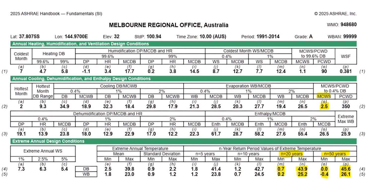
Fig 1 – Weather data from ASHRAE Fundamentals / ASHRAE Weather Data Viewer (sample data for Melbourne regional office area)2
Figure 1 illustrates the ASHRAE climate design conditions for the Melbourne regional office, which serve as inputs for HVAC design and CFD simulations. Key data includes annual heating and cooling parameters, dehumidification conditions, and extreme annual design values, derived from long-term weather observations.
One important input to CFD studies is the mean coincident wind speed (MCWS), which is the average wind speed that occurs concurrently with peak temperature conditions. These wind speeds (e.g., 2.5m/s in this dataset) are essential to simulate realistic airflow patterns around equipment and buildings, which in turn affect airflow distribution, heat rejection performance, and potential uplift forces on equipment like chillers.
Note: Some clients may request the analysis to be based on the peak wind speed for a specific ambient temperature instead of the MCWS.
Additionally, the table includes extreme temperature values based on return periods such as n=20 and n=50 years, which refer to the statistical probability of certain temperatures occurring once in 20 or 50 years. These values (e.g., 43.9°C max DB for n=20 years) are used in CFD to model worst-case ambient scenarios that help test the resilience of mechanical systems under extreme heat events.
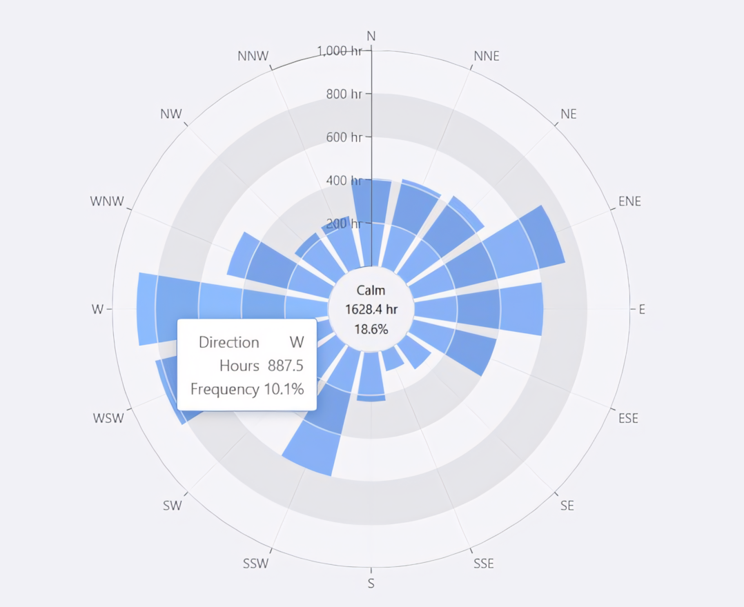
Fig 2 – Sample wind data from ASHRAE Fundamentals / ASHRAE Weather Data Viewer (sample data for Melbourne regional office area)2
Figure 2 illustrates the annual wind direction frequency for the Melbourne regional office area, derived from the ASHRAE Weather Data Viewer. The chart shows the dominant wind patterns, with calm conditions occurring approximately 18.6% of the time. This data is essential for defining boundary conditions in CFD simulations. The prevailing wind directions will guide the setup of airflow scenarios that may impact heat recirculation and subsequently influence the temperature uplift of outdoor equipment such as chillers, AHUs, and condensers.
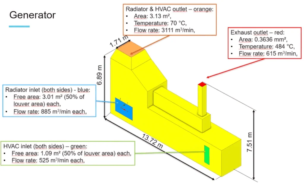
Figure 3 illustrates how generator units are represented as inputs within the external CFD model. Each unit is defined by parameters such as heat rejection, airflow direction, and velocity. Similar inputs will be applied to other equipment – such as chillers, AHUs, and condenser units – that may influence air recirculation and temperature uplift across the chiller array.
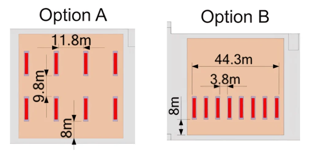
Figure 4 illustrates two rooftop chiller arrangement options serving a data hall, within a project comprising multiple data halls. During the preliminary design phase, CFD simulations are typically conducted to assess various configurations in terms of thermal performance, airflow dynamics, and operational efficiency. Once the optimal rooftop arrangement is identified, a detailed CFD analysis is carried out to validate and optimise the final design.
For the purpose of the CFD model, only general geometric representations are required to capture the key airflow and thermal interactions. Simplifying the model where possible is essential, as excessive detail can significantly increase computation time, reduce solver stability, and in some cases, cause the simulation to fail. The goal is to strike a balance between accuracy and efficiency by including only the geometry necessary to represent the physical phenomena being analysed.
Findings and results from representative CFD scenarios
Following the preliminary CFD simulations, the results are evaluated by comparing temperature uplift and recirculation percentages across the various chiller layout options. The chiller plant arrangement is then selected based on the configuration that demonstrates the lowest uplift and minimal recirculation under predominant wind conditions.
Upon finalisation of the chiller plant layout, a detailed CFD analysis is conducted, incorporating all critical equipment and multiple wind directions as described in the design methodology. The refined results are assessed to identify the chillers experiencing the highest average temperature uplift and to determine the corresponding wind direction responsible for this condition. Additionally, the average uplift across all chillers serving each data hall is calculated to assess the overall performance impact and guide any necessary mitigation strategies.
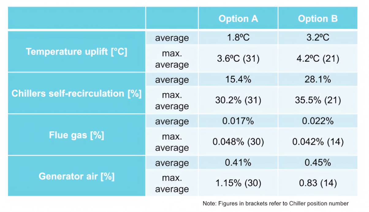
Fig 5 – Sample results from the preliminary CFD analysis of options A and B1
Figure 5 shows a table summarising the average results across all chillers, along with the maximum average value recorded for an individual chiller, indicated in brackets with the corresponding chiller number. These results are based on two different rooftop chiller arrangements. As shown, option A demonstrates a lower average temperature uplift compared to option B. Furthermore, option A also records a lower average recirculation percentage, making it the more effective configuration. Consequently, option A will be adopted for the project.
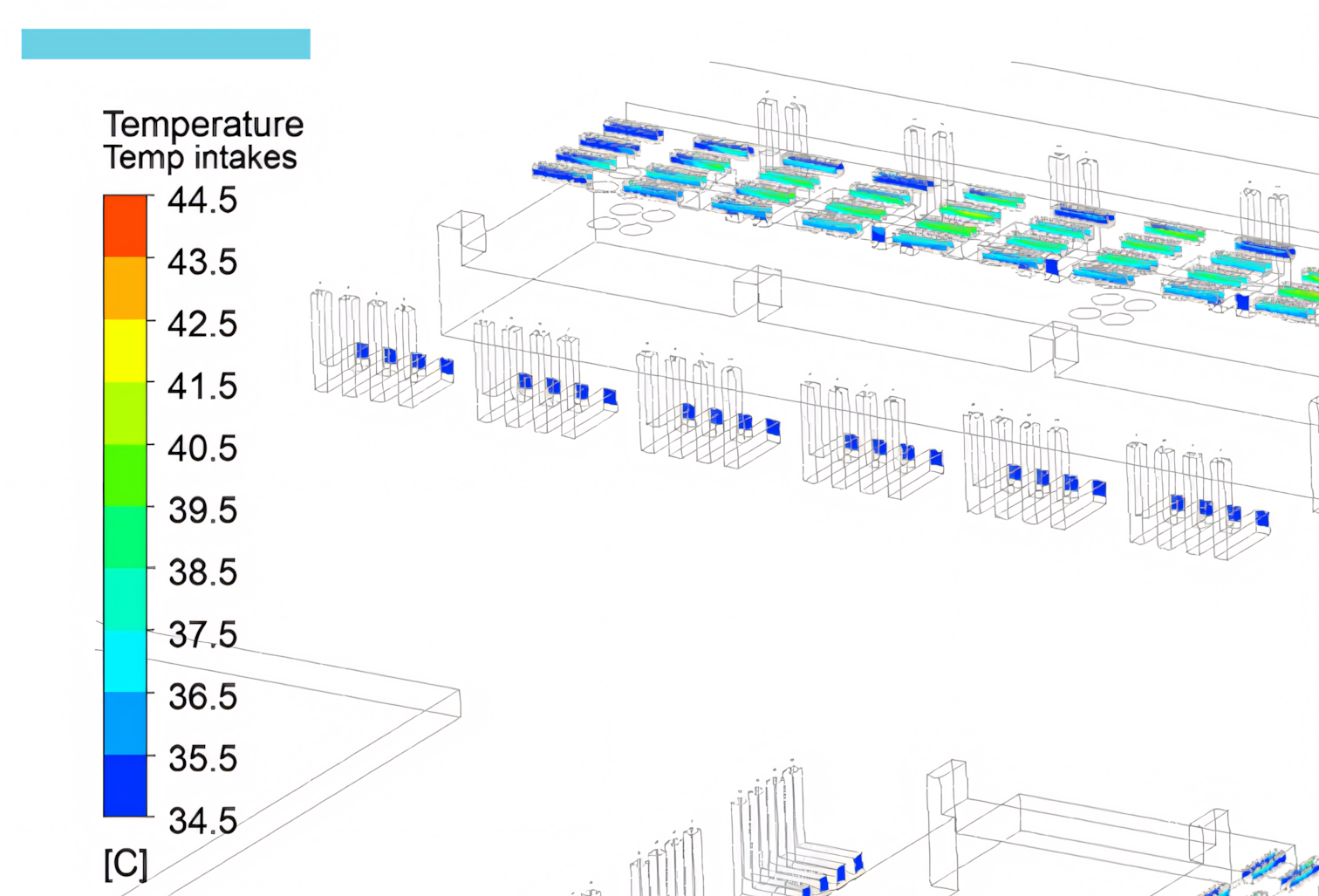
Fig 6 – Sample results with temperature intakes1
Figure 6 illustrates the actual results derived from the CFD model for the sample project. The chillers and other equipment are incorporated into the model, and the image shows the temperature intake for each chiller.
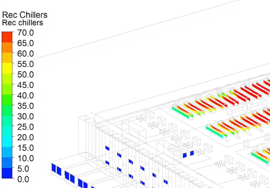
Fig 7 – Sample results with recirculation percentage1
Figure 7 illustrates the actual results derived from the CFD model for the sample project. The chillers and other equipment are incorporated into the model, with the image showing the percentage of exhaust air recirculation to the chiller intake. Similar analyses will be conducted for generator air recirculation and other equipment.
Assessment of chiller performance impacts
Based on the CFD results and the chiller performance data provided by the manufacturer, the derated cooling capacity of the chillers and the overall system capacity for the data centre facility are assessed against the client’s basis of design (BoD) and the permittable excursion limits.
The impact of any capacity reduction due to temperature uplift or recirculation is assessed in relation to the facility’s performance criteria and resilience expectations. Usually, operators or data centre clients permit defined excursion limits – where internal temperatures are allowed to exceed design thresholds by a specified margin and duration. These criteria provide flexibility in responding to short-term environmental conditions without compromising overall system reliability. Therefore, the CFD results are analysed not only to identify potential performance degradation but also to ensure that any excursions remain within acceptable operational limits.4,5
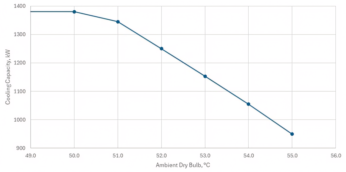
Fig 8: Sample selected chiller capacity against temperature1
Figure 8 illustrates the capacity derating of the selected chiller as a function of temperature. This data, typically provided by the chiller vendor, is used to analyse the derating effect of chillers at different temperatures. In this case, the selected chiller has a capacity of 1.38MW at 50°C.
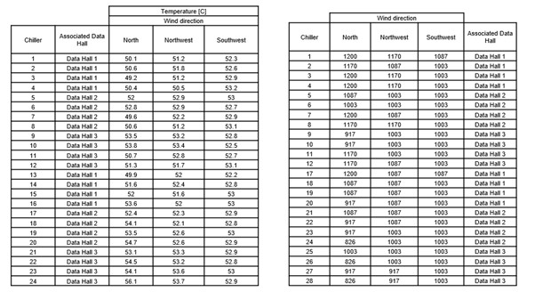
Fig 9: Sample results – resultant air intake temperatures and resultant chiller cooling capacity
Figure 9 presents the results from a detailed CFD analysis conducted after finalising the rooftop chiller arrangement. The sample project consists of three data halls, with a total of 24 chillers. The CFD simulation was performed for three different wind directions, including the predominant wind direction. The results show the inlet temperature at each chiller and the corresponding capacity derating for each unit. In this case, the selected chiller capacity is 1.2MW at 50°C.
Mitigation strategies informed by CFD analysis
If the results indicate acceptable performance – i.e., minimal temperature uplift and negligible impact on chiller capacity and system availability – no mitigation measures are required. However, if the analysis reveals significant average temperature uplift leading to substantial derating of chiller capacity and a corresponding increase in potential downtime hours, mitigation strategies must be considered. In such cases, the CFD analysis will be revised and re-run to assess the effectiveness of the proposed modifications.4,6
Typical mitigation measures include:
- Increasing the spacing between chillers to improve airflow.
- Increasing the height of chiller discharge, by means of extended discharge cowls. These may also incorporate discharge attenuation properties.
- Extending a screen over the entire roof chiller compound, to prevent recirculation due to downdrafts. This could take the form of an open-sided horizontal rain screen that has cut-outs for chiller discharge but still permits air intake from the sides.
- Consider the introduction of fins extending from the perimeter of the roof. These can sometimes assist in conveying the warm, wind-driven discharge plume away from the building, thereby minimising the risk of recirculation.
- Wind barriers to prevent warm air migration from one side of the building to another.
- Raising the height of generator exhaust chimneys to minimise thermal interference.
- Reviewing and optimising the placement of adjacent equipment such as condensers, generators, and AHUs to reduce recirculation effects.
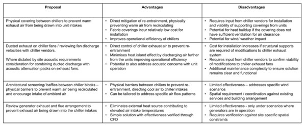
Fig 10: Sample mitigation strategy developed for discussion with client1
Figure 10 shows a mitigation strategy table developed for a data centre project to improve chiller intake temperatures.
Conclusion
With the increasing deployment of high-density racks in AI-driven data centres, the demand for air-cooled chiller systems has grown significantly. This, in turn, has led to higher equipment density on rooftops, increasing the risk of thermal recirculation and temperature uplift, both of which can adversely impact chiller performance and system reliability.
External CFD analysis has become a critical design tool in understanding the complex interaction of wind patterns, thermal plumes, and equipment layout in such mission-critical environments. By applying site-specific climatic data and detailed equipment modelling, designers can identify potential performance risks early in the design process.
This paper has discussed the methodology, design criteria, and outcomes of external CFD analyses conducted across various classified data centre projects. Although no specific project data has been used, the insights are based on real-world design experiences. The analysis highlights the importance of evaluating chiller uplift temperatures and recirculation zones to ensure the system meets the client’s basis of design and availability targets.
Where performance risks are identified, mitigation measures such as increasing chiller spacing, adjusting equipment heights, and revising rooftop layouts can significantly improve thermal performance. Re-running CFD simulations with these modifications ensures that the final design supports optimal chiller operation, safeguards uptime requirements, and enhances the resilience of the overall cooling infrastructure.
As the data centre industry continues to evolve with higher cooling demands, integrating external CFD analysis into the design workflow remains essential for delivering efficient, reliable, and scalable cooling solutions.
While this paper focuses on the external CFD implications for air-cooled chillers, it is important to note that similar airflow and thermal interaction challenges also apply to other forms of heat rejection systems, particularly evaporative cooling solutions such as cooling towers. These systems introduce added complexity, as their performance is strongly influenced by the prevailing wet bulb temperature rather than dry bulb alone. Although evaporative cooling tends to be more effective in terms of heat rejection and typically requires a smaller physical footprint – allowing for greater spacing between units – this benefit comes with increased water consumption. More critically, these systems are highly sensitive to moisture-laden recirculated air. Any recirculation of moist exhaust back into the cooling tower compound can locally increase the wet bulb temperature, leading to a significant derating of system capacity. As such, CFD analysis becomes even more essential in identifying and mitigating recirculation risks in installations that rely on evaporative cooling technologies.
About the author
Priyatharsan Sachchithanantham, M.AIRAH, is a chartered engineer with over 13 years of experience in the construction industry, including nine years in Singapore. He has held roles across both contractor and consultancy environments, specialising in HVAC systems. He is currently working as a senior mechanical engineer at Cundall, focusing on data centre design and delivery.
Most recently, he acted as the deputy mechanical lead on a hyperscale data centre project in Melbourne that featured liquid cooling technology. Priyatharsan’s broad project portfolio spans data centres, residential developments, aged care facilities, hospitality, community recreation centres, and educational institutions.

Acknowledgements
The author used Ansys Fluent CFD software to generate the data for this paper. The author also acknowledges:
Mentorship and guidance by: Malcolm Howe BEng (Hons) CEng MCIBSE MIEI ASHRAE – Partner, Critical Systems, Cundall London Office
Cundall CFD team:
- Mariusz Szlenk – Principal Engineer
- Ewa Jaszczyszyn – Senior CFD Engineer
Cundall critical systems team:
- David Dryden – Partner, Melbourne
- Benny Cheah – Director of Building Services, Melbourne
- Gosia Cebula – Associate Director, London
- Jerome Felicks – Associate Mechanical Engineer (Critical Systems), Chennai
- James Wild – Principal Mechanical Engineer (Critical Systems), London
- Liam Kearns – Senior Mechanical Engineer (Critical Systems), Sydney
- Mohammed Islam – Mechanical Engineer, Melbourne
- Abhishek Tomar – Mechanical Engineer (Critical Systems), Chennai
References
- Actual data centre projects
- ASHRAE Fundamentals 2021 & 2025
- ASHRAE TC 9.9 Datacom Encyclopedia – Design Considerations for Datacom Equipment centers – 6.3.1 External CFD Modeling
- UptimeInstitute – Data Center Site Infrastructure Tier Standard: Topology
- https://eolios.eu/data-center/data-center/external-internal-cfd-data-center-hyperscale/
- https://eolios.eu/data-center/external-cfd-simulation-for-data-center/


Latest edition
See everything from the latest edition of Ecolibrium, AIRAH’s official journal.