Critical mass
According to CSIRO, storage of renewable energy is essential to ensure access to secure, reliable and affordable energy as Australia transitions to net zero by 2050. Part of that mix could be thermal energy storage (TES), a concept well established in the HVAC&R industry but often undervalued. Sean McGowan reports.
CSIRO’s Renewable Energy Storage Roadmap, released in March 2023, responds to common challenges around decarbonisation and technology readiness in Australia, and examines the potential of energy storage to support cost-effective decarbonisation in industry.
Above all else, it highlights the need to rapidly scale up a diverse portfolio of storage technologies to keep pace with rising demand and realise opportunities in the market.
“Although there are existing storage systems used to deliver energy from fossil fuels, higher levels of renewables in Australia’s energy system will result in a greater requirement for renewable energy storage technologies,” says the report.
“These include electricity storage through electrochemical processes (e.g., batteries), mechanical storage ((e.g., pumped hydro energy storage), chemical storage ((e.g., hydrogen in tanks or pipelines) and thermal storage (e.g., molten salts).”
Of course, thermal energy storage (TES) is nothing new.
In its simplest form, it refers to systems that convert and/or store an energy input – be it heat or electricity – in the form of thermal energy, which can be used later in the form of thermal energy.
Although the report does not explore water tank TES or the use of low-temperature TES, the potential of these technologies in helping to decarbonise the HVAC&R industry cannot be understated.
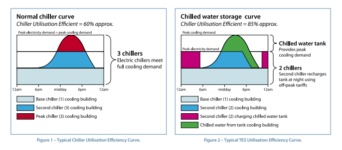
The most common example is the concept of chilled water thermal energy storage (TES) whereby chilled water is generated overnight when the chilled water demand within the building is significantly reduced and/or the electricity tariff is low.
This chilled water is then stored in a large insulated vertical tank for use the following day. This is graphically depicted in the following diagrams:
Electricity pricing is a key factor in the whole-of-life cost-benefit analysis of chilled water storage systems and their financial justification in a project.
The principal application of these systems is to shift the energy and demand-load requirements associated with chilled water generation to overnight during off-peak hours. Yet as part of an overall energy/operational cost saving strategy, they do offer a number of other advantages including whole-of-life cost, reliability, redundancy and environmental benefits (see breakout).
Chilled water storage has also been used in combination with CO2 heat pumps to maximise the use of onsite renewable energy generation, while some industrial processes use smaller scale systems to eliminate peak process load impacts that would otherwise require significantly larger chilled water systems to meet peak cooling demands.
Other forms of TES have also been successfully applied in association with HVAC&R.
These include fabric energy storage systems such as thermal labyrinths, slab heating or cooling and phase change materials within the building fabric itself like plasterboard. Thermal labyrinths and fabric energy storage typically utilises night purge strategies that use cooler overnight ambient air to remove heat stored within a building to prime it for the next day, although a range of other strategies can be used effectively.
Conversely, concentrated solar thermal systems use rooftop solar systems to collect heat for space heating and cooling via heat exchange.
Then there are ground-source systems – closed loop or open loop – that achieve heat transfer from water taken or circulated through a borehole or water body.
“Simple, tried–and–tested technologies like thermal labyrinths and night purging for example should form part of our collective design system thinking”
Chilled water TES advantages
Whole-of-life cost
Although chilled water storage systems require increased up-front capital expenditure to integrate, they can offer quick payback periods of between three and eight years if sized and operated to their maximum potential.
The short payback is being achieved through a combination of the following economic benefits:
- Reduced initial capital costs of required chilled water plant as a TES system can take the place of at least one chiller.
- The TES system can also be part of meeting the redundancy and resilience requirements of the development, further reducing the up-front capital costs.
- Lower replacement costs for chillers by virtue of less chillers being needed to meet peak cooling demand and the TES system having a greater than 50-year economic life.
- Savings of up to 1.5 per cent on energy use and associated greenhouse gas emissions due to better energy management and minor improvement of chiller operational efficiency due to lower overnight temperatures.
- Lower energy usage costs because the TES system is charged overnight using off-peak electricity and reduced peak electrical demand costs.
- The reduced number of chillers within the overall chilled water plant can also have the further benefit of reducing the required electrical supply connection.
Reliability
TES systems have a significantly longer life span than electric chillers, in some cases greater than 70 per cent (i.e., 50 years as compared to 25 years). TES systems also have fewer moving parts, offering benefits in improved reliability.
Redundancy and Back-up
The presence of a TES system offers improved redundancy and back-up of the chilled water system.
Environmental Benefits
TES systems offer a number of environment benefits including reduced use of CFCs and HCFCs due to reduction in overall installed chiller plant capacity, and reduced greenhouse gas emissions from chillers operating during cooler overnight temperatures.
Other benefits include reduced peak electrical demand, offering lower greenhouse gas emissions and sulphur dioxide emissions at power stations, as well as lower transmission losses of electricity as overhead lines incur line losses, which increase as the outdoor air temperature increases.
The chilled advocate
Some of the most successful examples of TES in the Australian context have been operating for more than 20 years, such as the chilled water storage system at Charles Darwin University’s Casuarina campus.
This was the first working example that Caimin McCabe, M.AIRAH, principal sustainability consultant at Stantec was exposed to, after attending a presentation on the system when working as an ESD and energy adviser for the Northern Territory government.
“From this briefing and introduction to TES systems and their life cost, redundancy and resilience benefits, I became an advocate for their consideration on projects, regularly pitching their inclusion through the preparation of information papers and feasibility studies on their cost and paybacks,” says McCabe.
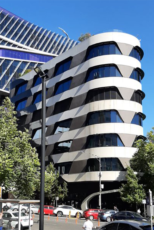
When working as the state ESD adviser for the Victorian Comprehensive Cancer Centre (VCCC), McCabe advocated for the installation of a small-scale TES as part of the public private partnership (PPP) project’s briefed requirements.
Despite some push-back around the operational cost-benefits of the system, it was ultimately installed. And it has proven to be very useful in offering an effective means of taking chillers offline for maintenance within the critical care facility – an operational benefit not factored into the initial business case.
Since joining Stantec, McCabe has championed an investigation into the potential integration of TES at Melbourne University’s Werribee campus as part of the university’s Smart Campus Energy Upgrades Program.
How have changes to electricity pricing structures impacted TES systems?
Utility companies changing their pricing structures by reducing the cost difference between peak and off-peak electricity usage charges – as well as bringing in more fixed components to how they charge for peak electrical demand – makes it more difficult to assess the long-term viability of demand management and load-shifting strategies such as chilled water storage.
The differing approaches being adopted by different utility companies further complicates decision making as well.
Although, with the rapid transitioning to all-electric servicing for new and existing buildings the impact on peak demand is coming more and more to the fore, as it is evident that the existing infrastructure cannot meet the projected demand. In consideration of this, we have seen some network distributors thinking laterally on how to address this by offering lower network connection costs if buildings offer the ability for them to have onsite solar energy storage.
While we may also see utility companies change their pricing structures to encourage more demand management and load shifting, as this may affect their revenues I would not envisage this happening without external pressure to do so.
However, for large organisations with precincts, such as universities, the issue is being considered more holistically, with other financial factors such as ongoing replacement and maintenance costs coming into their thinking. This is helping to get chilled water storage systems across the line.
Where can chilled water TES solutions be used in a broader sense?
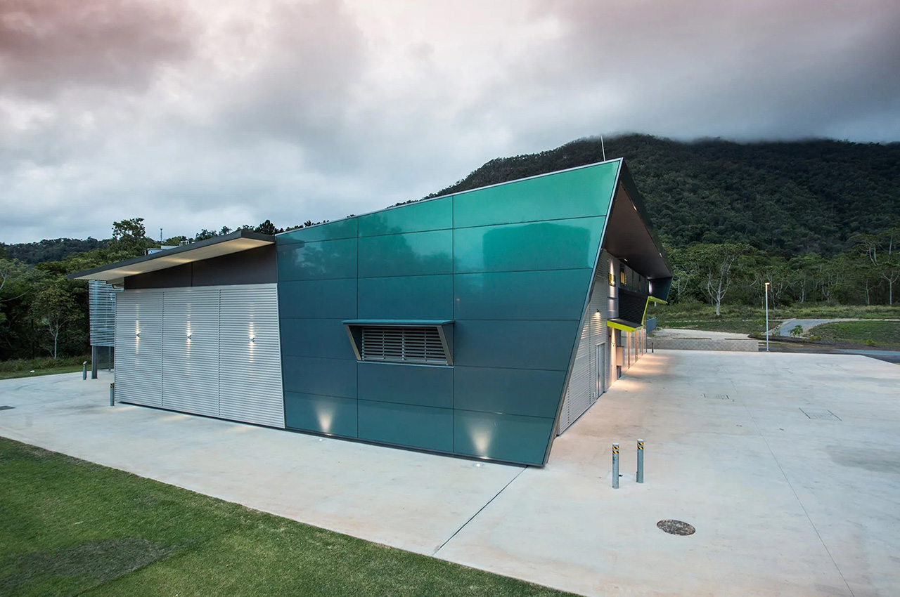
Due to scale, particularly when the full benefits are being sought, they best suit being integrated within a campus or precinct central energy solution, such as the Campus District Cooling (CDC) system at the Cairns Campus of James Cook University.
Although they would also offer significant whole-of-life, redundancy and resilience benefits to a hospital as well, considering the limited real estate typically available within large hospitals, they are difficult to justify, as was found for both the Box Hill Hospital redevelopment and the new Royal Children’s Hospital in Melbourne.
While smaller systems could be considered when factoring in the associated capital cost and whole-of-life cost benefits achievable, the paybacks are longer, thus making them more difficult to justify.
How can TES concepts be used to further decarbonise the grid?
While all TES technologies can offer improved energy efficiency to varying degrees, the biggest benefit to decarbonising the grid would be their demand-management benefits, which will allow the progressive greening of the grid to have greater overall impact.
Also, although designers can be easily distracted by the latest new innovation, it is important that we do not lose sight of older TES technologies, solutions and approaches. Simple, tried-and-tested technologies like thermal labyrinths and night purging for example should form part of our collective design system thinking. Similarly, the use of both ground and water source geothermal systems, particularly smaller systems should be adopted more often.
From the ground up
As a pioneer of the ground-source heat pump industry in Australia, GeoExchange Australia has harnessed the capability of thermal energy storage in a range of projects.
According to GeoExchange Australia managing director Yale Carden, M.AIRAH, the more conventional approach is to locate the TES between the heat pump(s) and the building distribution system.
“TES is used for hot and chilled water storage on many of our projects,” Carden says.
“This thermally balanced system is a significantly lower cost to install and operates more efficiently. The TES functionality of the GHX is at the core of this.”
“However, our primary interest lies in where we locate the TES, in the form of a ground-source heat exchanger (GHX) or aquifer thermal energy storage (ATES), before the heat pumps. As the source of thermal energy for the heat pumps, the GHX/ATES has dual functions of heat exchanger and TES.”
The heat exchanger function of the GHX makes use of shallow ground temperatures that closely correlate to average ambient temperature for any given location courtesy of solar radiation. This provides the heat pump(s) with a more stable and consistent source/sink.
“The TES function of the GHX also relates to the influence of solar radiation, but is enhanced by closing the building’s thermal energy loop rather than discharging to ambient.”
For example, thermal energy (heat) rejected to the GHX during the cooling cycle is stored and can be utilised later for heating. This storage time range from the instantaneous to the seasonal.
According to Carden, the power of this TES capability is evident in a number of GeoExchange Australia’s projects – especially for buildings and climates where a mix of heating and cooling is required.
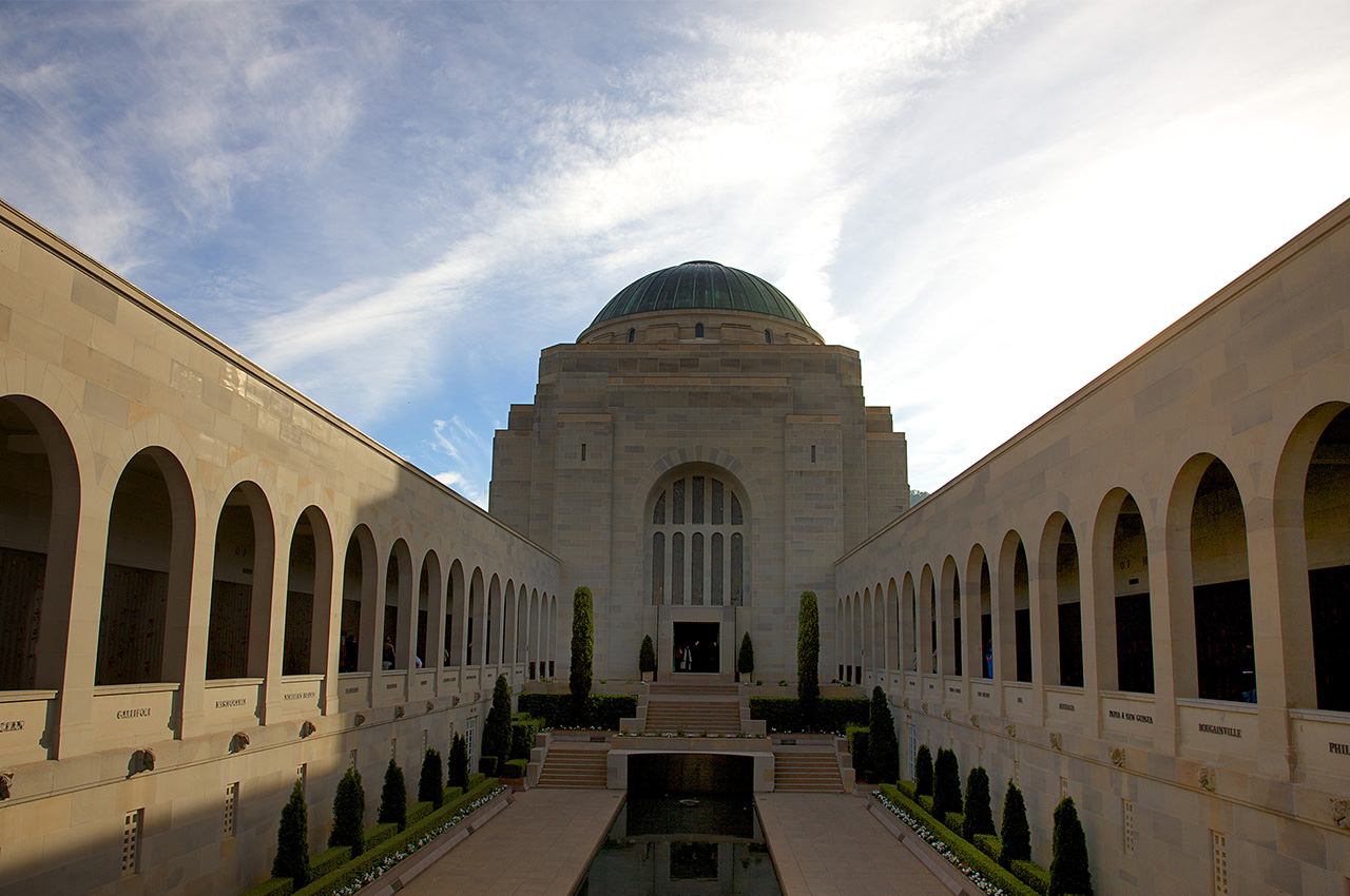
A comparison of two buildings – the CSIRO ASKAP project in northern Western Australia, and the Australian War Memorial Redevelopment in Canberra – best illustrates this. The CSIRO ASKAP project was designed for 100 per cent cooling in 27˚C ground, whereas the Australian War Memorial Redevelopment was thermally balanced using a hybrid GHX in 18˚C ground.
“For a normalised 120m deep GHX, the former was capable of approximately 2.7kW per borehole on a 24m spacing (22.5W/m), “ explains Carden, “while the latter was capable of approximately 11kW per borehole on a 5m space (92W/m).”
The key difference here is that through the combination of building load, climate and hybrid design, as much thermal energy from the GHX is extracted as is rejected.
“This thermally balanced system is a significantly lower cost to install and operates more efficiently,” Carden says. “The TES functionality of the GHX is at the core of this.”
How does the concept of TES differ between the demand side and the supply side?
Both types of storage have the common objective of energy arbitrage. This is, charge the storage system when energy is cheap or available and utilise it later when needed and/or costs are higher.
Aside from end use, the main difference are temperature, the materials utilised and the unilateral or bilateral flow of energy.
Supply-side systems tend to be higher temperature (i.e., hundreds of degrees Celsius), utilise materials such as aluminium, sand, graphite and others in development, and are unilateral flow systems. This is, electrons are created, stored and then utilised as required. The storage is mostly about energy arbitrage.
Demand-side systems vary their temperature depending on heating (40–90˚C) or cooling (5–10˚C), utilise materials such as water and phase-change materials (PCMs) and can be bilateral-flow systems.
The capacity for the bilateral flow of energy in a demand-side thermal system provides the greatest opportunity for energy conservation.
How common is TES in the built environment?
TES is already commonly used in domestic hot water systems, hydronic heating and in the concept of thermal mass, so arguably it is both common and mainstream.
Its application for heating and cooling follows the principles of energy arbitrage, with the potential benefit of energy conservation.
Major barriers – to its broader uptake – are physical space and cost. TES requires storage tanks and somewhere to put them. When replacing a gas boiler, that doesn’t require such storage, so this can be problematic.
In terms of cost, storage tanks are relatively cheap on a kW basis for hot/chilled water systems but more thermally effective options such as PCMs are not.
A further barrier exists in the absence of sophisticated business cases that can properly model the combination of electrical and thermal energy arbitrage and the subsequent role of both electrical and thermal energy storage. We are currently conducting a research project with the University of Wollongong in this area and will have results out towards the end of the year.
Storage in action
Proving location or climate is not a governing issue as to the suitability of a thermal energy storage solution, a number of TES systems exist around the country – from the tropics of far north Queensland to the southern states.
Charles Darwin University, Darwin NT
In 1997, Charles Darwin University’s Casuarina campus (then known as the Northern Territory University) was a major consumer of electricity in Darwin, with a peak electrical demand of 4.8MW and a maximum demand of 5.2MW recorded the year prior.
Located in an area that was undergoing significant development and growth, the university was approached by the local electricity supply authority and offered incentives such as an alternative tariff structure with lower electricity rates to reduce the campus’ maximum electrical demand by 1.5MW.
The reduction could only be achieved by shifting the full chiller load operation to after hours, or off peak. To facilitate this change, a large-scale thermal energy storage (TES) tank was constructed.
The system comprises two main features: a chiller plant that generates the chilled water that is then stored in the TES tank, and the site reticulation and pumping system that circulates the chilled water across 80,000m² of air conditioned space.
At the time of commissioning, this was the largest TES system of its kind in the southern hemisphere, with a total tank capacity of some almost 8.6ML.
It is now 25 years since the TES system was successfully commissioned at Charles Darwin University’s Casuarina campus, and despite changes to the system over that time, remains as operationally effective as ever.
James Cook University (JCU)
In 2009, the Cairns campus of James Cook University (JCU) represented a typical small to medium-sized campus, comprising nine academic and service buildings with a total air conditioned floor area of approximately 25,000m².
Located in the coastal tropics, peak summer air conditioning loads are high, with a year-round requirement for cooling. Annual energy usage of air conditioning systems is therefore high, and represents a significant part of the university’s operating costs.
From 2010, the university planned to embark on a major expansion program that would result in the construction of 10 new buildings over several years on the Cairns campus, effectively doubling the air conditioned floor area.
As the aged chiller plant could not be upgraded without substantial capital cost, it was decided to future proof the campus by constructing a new Campus District Cooling system including a central energy plant (CEP) to house high-efficiency chillers and cooling towers and an adjacent 9ML thermal energy storage (TES) tank.
TES makes use of periods of the day or night when the site demand for cooling is less than the average demand. During these times the central chilled water plant cools return water (15°C) back to chilled water (6°C). During times when the site demand exceeds the average demand (typically in the afternoon), the chilled water is drawn from the storage tank.
From here, the pre‐cooled water is then reticulated throughout the campus and delivered to air conditioning air handling units within each building.
Since the installation of the TES system at the Cairns campus, it has contributed to a $3 million per year reduction in the university’s electricity costs.
Source: James Cook University
CSIRO ASKAP, Murchison region WA
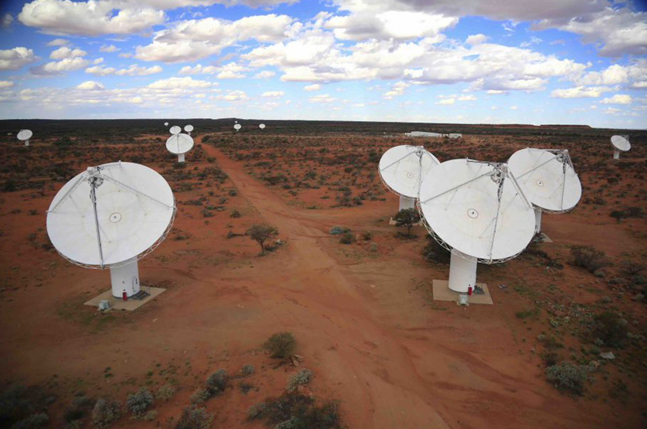
Located 350km north-east of Geraldton in mid-west Western Australia, the Australian Square Kilometre Array Pathfinder (ASKAP) opened in 2012 at the Murchison Radio-astronomy Observatory.
The remote site was selected by the CSIRO because of the region’s low population density and lack of man-made radio signals.
ASKAP features 36 12m-diameter dish antennas that work together as a single instrument.
It is a pathfinder for the international Square Kilometre Array (SKA) project, which aims to answer some of the most fundamental questions asked by modern astronomy and physics.
Pioneered by the CSIRO, the technology employed by ASKAP is able to survey the whole sky with unprecedented sensitivity. However, it also produces data at terabytes-a-second speed, which is then handled by onsite custom super-computers before being sent via optical fibre to CSIRO sites in Geraldton and Perth.
Such is the amount of data created by ASKAP that it is impossible to store it all. Rather, algorithms have been created to process data “on the fly”, creating final complex – but much smaller – data “cubes”. This computer power a heat load that makes heat rejection in the forbidding environment challenging.
With a peak heat load of 390kW – the majority of which is due to computing equipment – the task of rejecting this heat while maintaining a radio-quiet environment presented challenges. And the site’s weather conditions coupled with the requirement for a radio-quiet environment all but ruled out traditional water-cooled and air-cooled plant options.
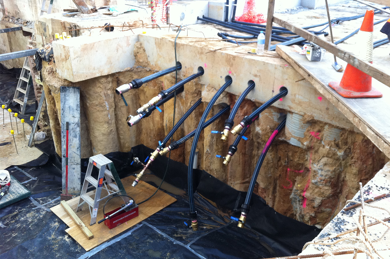
A ground-source heat exchange (GHX) system was ultimately the preferred option, based on the advantages it offered in terms of RFI emissions and energy efficiency.
The final system comprises 96 boreholes across a field covering 45,000sq m, each borehole measuring 125mm in diameter and drilled to a nominal depth of 124m using equipment specially shipped out from Europe for the project.
At the time, it was Australia’s largest cooling-only GHX installation.
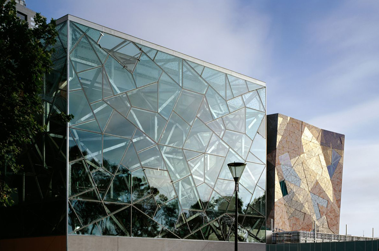
Federation Square, Melbourne VIC
Melbourne’s Federation Square has certainly enjoyed its share of controversy over the years, but it continues to have sustainability at its heart.
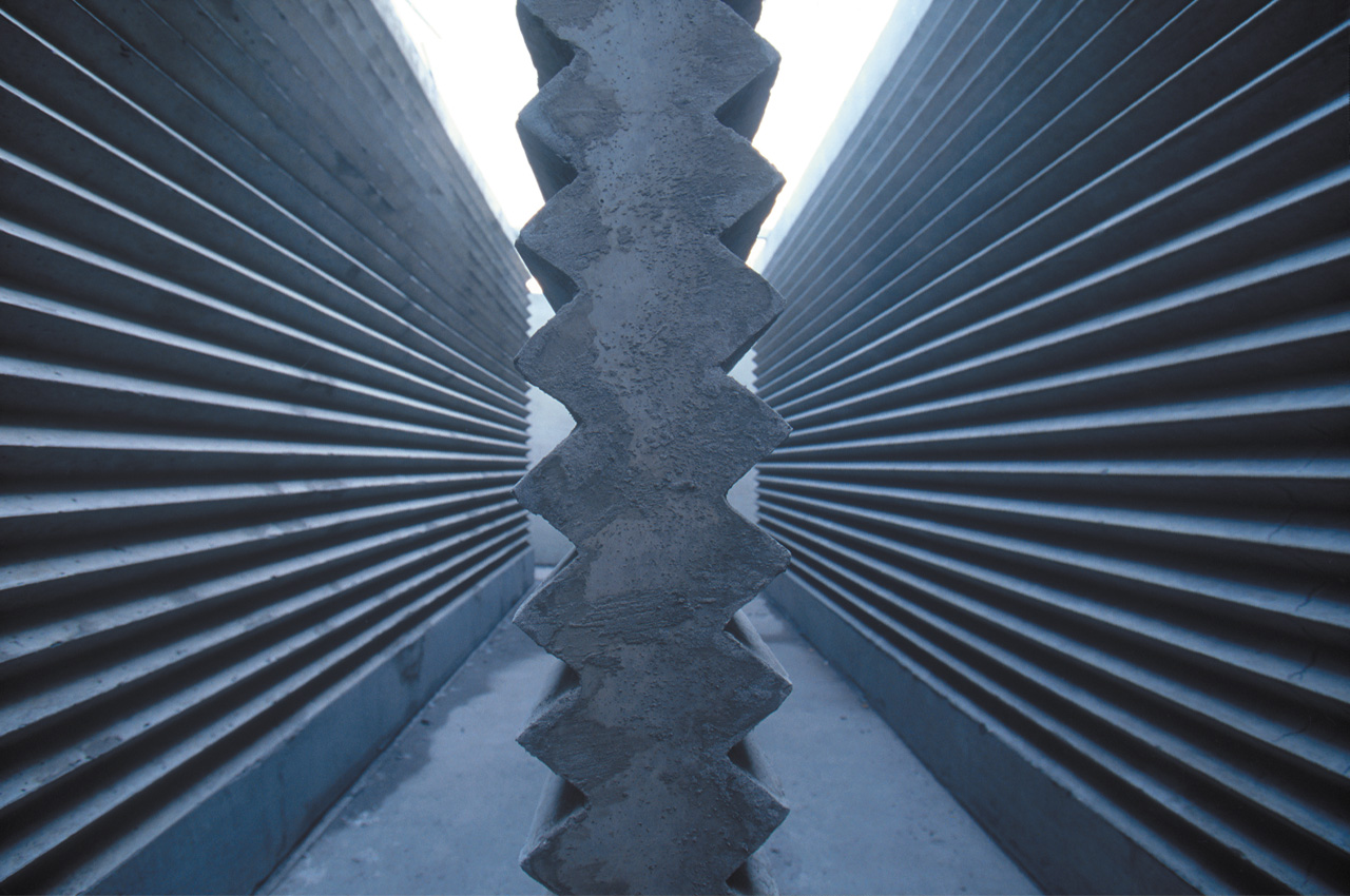
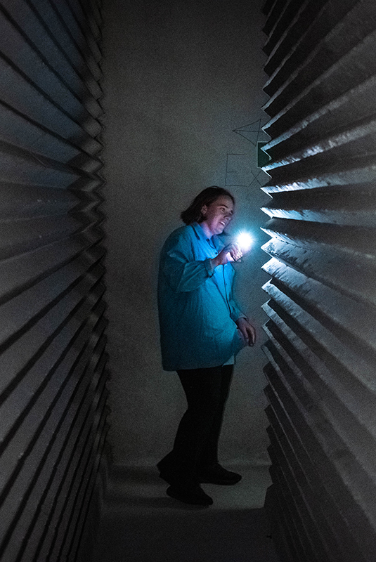
Beneath the coruscating and jagged panes of the Atrium lies a decoupled thermal mass design – otherwise known as a thermal labyrinth.
Decoupled thermal mass storage is a term used to describe the ability of a material to absorb or store heat outside a building, releasing it when required. Labyrinth systems consist of a maze built from materials with a high thermal mass, such as concrete, that use air to transfer the thermal storage capacity of the labyrinth to the building.
In the middle of the Federation Square site is a 40m x 40m 1.4km long labyrinth that provides structural support to the plaza, cooling to the Atrium, and pre-chilled air to the mechanical systems for other onsite buildings.
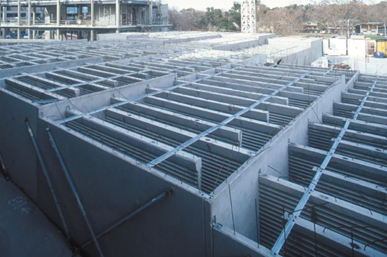
The labyrinth was designed to achieve up to 12°C cooling of external ambient air in summer, and 7°C heating in winter.
In summer, the labyrinth is cooled by night air coming off the Yarra River. Air is moved through the labyrinth, cooling down the 3m high corrugated pre-cast concrete walls to the lowest night-time temperature. During the day, warm ambient air is ventilated into the labyrinth and is cooled as it comes in contact with the chilled walls.
This air is then distributed into the Atrium. Warmer air in the Atrium is displaced and evacuated through vents in the ceiling.
Phase-change materials
Phase change materials (PCMs) can often go hand-in-hand with thermal energy storage, capable of storing or releasing large amounts of latent heat (energy) for use in cooling or heating.
As one of Australia’s leaders in the field of PCM research, development and application through collaboration with the University of South Australia’s Future Industries Institute, Glaciem Cooling Technologies has demonstrated the technical and economic value of this technology in commercial and industrial HVAC&R applications.
“Phase-change materials work by using the latent heat of the PCM rather than the sensible heat, but changing the state of the PCM from a liquid to a solid and back again,” says Glaciem Cooling Technologies managing director Julian Hudson, M.AIRAH. “An additional heat transfer fluid (HTF) is required to transfer the energy from the PCM to the load.”
Hudson says the most common PCMs used in HVAC&R are non-chloride and chloride-based salts added to water.
Currently undertaking a PCM TES project under ARENA’s Advancing Renewables program, Glaciem has completed the installation of three TES units incorporating PCMs at Montague Orchards, Reef HQ Aquarium and Pernod Ricard Winemakers.
An AIRAH Award winner in 2021, the successful integration of PCM TES technologies with CO2 heat pumps and cloud-based control algorithms at these sites indicates the potential to transform the energy profile of the HVAC&R industry.
“As we strive for net zero by 2050, HVAC&R systems, will have to operate economically as the grid transitions to more renewables and the use of natural gas for heating decreases,” says Hudson.
“Regardless of the process, renewables only work in conjunction with storage and smarts controls. Electrical batteries don’t stack up economically in HVAC&R, but thermal batteries (TES) do. I believe the HVAC&R systems of the future will operate like those we have installed under ARENA’s Advancing Renewables project. Otherwise, HVAC&R cannot operate economically with a decarbonised grid.”
Shots on goal
According to CSIRO chief executive Larry Marshal, there is no silver bullet for energy storage because it’s hard to beat the unique energy characteristics of fuels.
He calls for multiple “shots on goal” from a range of storage technologies.
“To ensure sustained progress towards net zero, we need a robust pipeline of projects that use diverse technologies supported by industry, government, research and community stakeholders,” Marshall says.
The HVAC&R industry already has a number of proven TES technologies available to it, many of which have been used effectively for decades. But will they continue to be undervalued?
“While I recognise it will be a challenge, considering how the industry currently operates,” says Stantec’s McCabe, “I would like to think that the need for climatically responsive building design to address the climate emergency we are facing will lead to greater use of TES technologies and solutions.
“However, this will need a much stronger collaborative approach to building design – one that reflects true whole-of-life systems thinking.”
Like to know more?
Read more about Glaciem’s TES installations in Ecolibrium April 2022.
Go to theecolibrium.com or www.airah.org.au/ecolibrium.
This article appears in Ecolibrium’s June-July 2023 edition
View the archive of previous editions


Latest edition
See everything from the latest edition of Ecolibrium, AIRAH’s official journal.